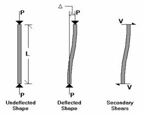
When a model is loaded, it deflects. The deflections in the members of the model may induce secondary moments due to the fact that the ends of the member may no longer be co-linear in the deflected position. These secondary effects, for members (not plates), can be accurately approximated through the use of P-Delta analysis. This type of analysis is called "P-Delta" because the magnitude of the secondary moment is equal to "P", the axial force in the member, times "Delta", the distance one end of the member is offset from the other end.
Since RISAFloor is designing entirely for gravity loads it does not need to account for the P-Delta effect. However, elements of the lateral force resisting system do need to consider this effect when being designed for lateral forces.
For additional advice on this topic, please see the RISA Tips & Tricks webpage at risa.com/post/support. Type in Search keywords: P-Delta.
Note
Standard Nodal Shear Method
The actual modeling of these secondary moments is done through the calculation of secondary shears (shown as V in the diagram):
P * Δ = V * L
so, V = P * Δ / L
Geometric Nonlinear Stiffness Method
Unlike the Standard Nodal Shear method, the Geometric Nonlinear Stiffness Method does not apply any nodal shear load to the member, instead, the stiffness matrix of the structure is directly modified to consider reduction of stiffness due to axial loads. This method is based on approach by Chen, W. F. and Lui, E. M., Structural Stability: Theory and Implementation (1987).
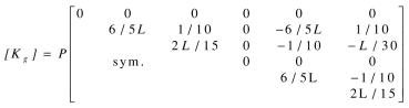
Similar as the Standard Nodal Shear Method, this method also requires an iterative procedure. In Step one, the linear static equilibrium equations are solved for the original model. In step two, the internal axial loads obtained from step one are used to form the geometric stiffness matrices as shown below, where P is axial load and L is the member length. The geometric stiffness matrix includes both the P-Delta and P-Small Delta effects. The geometric stiffness matrix is then assembled with the original stiffness matrix to obtain an updated stiffness matrix which considers P-Delta effect. The equilibrium equations are re-solved to obtain the new internal forces/new geometric stiffness matrices, and this procedure is repeated until it converges.
P-Delta Divergence
For both methods, if the P-Delta process is diverging dramatically, it will be stopped before numerical problems develop and an error will be displayed. If this error is displayed, the P-Delta displacements have reached a level where they are more than 1000 times greater than the maximum original displacements. If this happens with your model, the model may be unstable under the given loads, or there may be local instabilities present. See P-Delta Troubleshooting and Testing Instabilities to learn how to solve these problems.
For additional advice on this topic, please see the RISA Tips & Tricks webpage at risa.com/post/support. Type in Search keywords: P-Delta.
The P-Delta algorithm in the Standard Nodal Shear Method is based on end-joint displacements and will not automatically account for the effect of interior span forces on members, or member end rotations. As such the RISA implementation of P-Delta can be referred to as a P-Big Delta analysis.
In addition to the P-Big Delta effect, there can also be a P-Little Delta effect caused by end node rotation or transverse loading between node points. Please refer to the P-Little Delta topic for more information.
Note
The P-Delta effect can be thought of as decreasing the flexural stiffness of members in compression and increasing the flexural stiffness of members in tension. It is possible that if you have members with extremely large tensile forces, and intermediate nodes that are not connected to supports or other "stiff" members, the P-Delta algorithm could cause a node displacement to reverse direction, instead of converging to zero. This is an incorrect result. (A practical example where this could happen would be a truss chord with a large amount of tension that also has extra nodes in-between the panel points.) If you have members with very large tensile forces, and intermediate nodes , you may want to do a "compression only" P-Delta analysis. You invoke this by putting a "C" in the P-Delta field, instead of a "Y". A "compression only" P-Delta analysis will only affect members that are in axial compression. The P-Delta analysis will not modify members that are in tension.
The default convergence tolerance is 0.5%. This means that the displacements from one solution to the next must vary by no more than ½ of 1 percent for the solution to be considered converged. You may adjust this tolerance on the Model Settings. If you have a model that does converge but takes a lot of iterations, you may want to increase this tolerance so convergence is faster. Be careful! If you set this value too high, unstable models may falsely converge. It is not advisable to set this value above 2 or 3 percent.
The first step in troubleshooting a P-Delta model that won't converge is to run the load combination without P-Delta analysis and make sure there are no instabilities. If it turns out that degrees of freedom are being locked, this indicates instabilities that you will want to fix.
In some ways, a P-Delta divergence may indicate an elastic buckling failure. Therefore, any P-Delta instabilities should be taken seriously and investigated thoroughly.
By far, the most common cause of P-Delta convergence problems is local instabilities. A local instability is when one part of the model is unstable causing the P-Delta analysis to diverge. To locate local instabilities, run the solution with P-Delta analysis turned OFF. Now plot the exaggerated deflected shape and animate it. Any local instabilities should be apparent. See Testing Instabilities for more information.
In some cases, a model may be so flexible that it is not possible to run a P-Delta analysis. A situation where this might occur would be a wood frame where all the connections were modeled as pins, but the boundary conditions did not provide positive lateral support. In the real world, the connections will take some moment and the structure would be fine, but in the idealized model, there is zero moment resistance at each connection. The total lateral stiffness would be very small and this would make convergence of a P-Delta analysis unlikely.
The Direct Analysis method requires a reduction in the axial and flexural stiffness of some members. This is done to account for the non-linear material effects caused by residual stresses. This stiffness reduction can be problematic during the early stages of design when your members may be smaller than they will be after basic drift and stress criteria are met. Therefore, RISA gives you the option (on the Codes tab of the Model Settings) to turn off this stiffness reduction or set it to a constant value (tau = 1.0).
In order to ensure that using LRFD load factors does not result in a penalizing effect for P-Delta analysis, the AISC 360-16 section C2.1.d (AISC 360-10 section C2.1.4) requires that the forces be multiplied by 1.6 during ASD analysis. Therefore, if AISC (360-05, 360-10, or 360-16) ASD is specified as the hot rolled code, RISA automatically multiplies all load combinations by 1.6 during solution, then divides the force results by 1.6 prior to displaying the results.
See the P-Little-Delta Topic.
The P-Delta effect is handled the same way for Wall Panels. The main difference is that the shears for a wall panel are only generated at the top, story, or the diaphragm locations. The average deflection at the story height (or diaphragm location) is used to calculate the P-Delta shears for the top and bottom of the story. These shears are then distributed over the width of the wall at those locations.
Note
Gravity columns and walls that are modeled in RISAFloor, but which are NOT included in the Lateral analysis will still have an effect on the P-Delta analysis in RISA-3D. This is because RISA-3D automatically includes this leaning column / leaning wall effect. This is done only for columns or walls that are contained within the a rigid diaphragm slab edge at that floor level. The program then uses the RISAFloor column / wall axial loads (without considering LL Reduction) along with the rigid diaphragm displacements (projected to each column / wall) to come up with equivalent leaning column shears for the diaphragm.
Note